<?xml version="1.0" encoding="utf-8"?><feed xmlns="http://www.w3.org/2005/Atom" ><generator uri="https://jekyllrb.com/" version="3.10.0">Jekyll</generator><link href="http://behindthepixels.io/feed.xml" rel="self" type="application/atom+xml" /><link href="http://behindthepixels.io/" rel="alternate" type="text/html" /><updated>2025-03-09T19:42:33+00:00</updated><id>http://behindthepixels.io/feed.xml</id><title type="html">Behind the Pixels</title><subtitle></subtitle><author><name>Edward Liu</name><email>shiqiu1105@gmail.com</email></author><entry><title type="html">Lens Matched Shading and Unreal Engine 4 Integration (Part 1)</title><link href="http://behindthepixels.io/Lens-Matched-Shading-and-UE4-Integration-P1/" rel="alternate" type="text/html" title="Lens Matched Shading and Unreal Engine 4 Integration (Part 1)" /><published>2017-01-18T00:00:00+00:00</published><updated>2017-01-18T00:00:00+00:00</updated><id>http://behindthepixels.io/Lens-Matched-Shading-and-UE4-Integration-P1</id><content type="html" xml:base="http://behindthepixels.io/Lens-Matched-Shading-and-UE4-Integration-P1/"><![CDATA[<p>Recently I have published a seires of articles on <a href="https://developer.nvidia.com/">developer.nvidia.com</a> about Lens Matched Shading and its integration into Unreal Engine 4. I am also reposting it here on my blog. The original post can be viewed at here: <a href="https://developer.nvidia.com/lens-matched-shading-and-unreal-engine-4-integration-part-1">Lens Matched Shading and Unreal Engine 4 Integration Part 1</a></p>

<h1 id="introduction">Introduction</h1>

<p>Lens Matched Shading (LMS) is one of the new technologies introduced along with the Pascal architecture, with the specific purpose of improving the performance and efficiency of Virtual Reality (VR) rendering. LMS achieves both better perf and perceived image quality than Maxwell’s Multi Resolution Shading (MRS) technique.</p>

<p>While LMS is quite simple and elegant algorithmically, there are many practical issues, optimization strategies and challenges to overcome when integrating it into an actual game engine. In this article, we have gathered the collective wisdom and experiences learned from integrating Lens Matched Shading into Unreal Engine 4 (<a href="https://www.unrealengine.com">www.unrealengine.com</a>), a fully featured game engine with source available.</p>

<h1 id="lens-matched-shading-intro">Lens Matched Shading Intro</h1>

<p><img src="/assets/images/lms_posts/image_0.png" alt="image alt text" class="align-right" width="300px" /></p>

<p>Before getting our hands wet in engine integration, let’s start with a short introduction to Lens Matched Shading. In the meantime, feel free to look at this blog done by my colleague Iain which covers the same topic as well: <a href="https://developer.nvidia.com/pascal-vr-tech">Pascal VR Tech</a></p>

<p>At the end of the rendering pipeline of all VR applications, one of the steps is lens distortion. It warps the rendered image according to the HMD lens profile, so that when you view the post-warped image through the lens, it appears to be undistorted again.</p>

<p>We define shading rate as the number of shading samples per unit area on the framebuffer. The side effect of this lens distortion is that it changes the shading rate of the original image drastically.</p>

<p><img src="/assets/images/lms_posts/image_1.png" alt="image alt text" class="align-center" /></p>

<p>As shown in the figure above, lens distortion significantly squashes the periphery of the image, while enlarging the center, which makes the periphery shading rate higher and the center shading rate lower compared with the original image.</p>

<p>The shading rate distribution after lens distortion is really far from ideal since the periphery receives many more shades per final sample than the central region. Also, viewers tend to focus their attention at the center of the screen, which places these over-sampled areas in their weaker peripheral vision.</p>

<p><img src="/assets/images/lms_posts/image_2.png" alt="image alt text" class="align-left" /></p>

<p>The figure below visualizes the shading rate distribution across a single view on an HTC Vive. It uses 1512x1680 as the actual render resolution and 1080x1200 as the display resolution. It’s clear that even with 140% of super sampling, the central region is still slightly undersampled on the final display, while the periphery is significantly super-sampled (close to 5x).</p>

<p>HMD lenses, like all other lenses, are designed to be sharper at the center and blurrier around the periphery. As we spend more time than necessary resolving shading in peripheral areas of the screen that are then blurred by optical distortions. Therefore if we could somehow control the shading rate to match the lens profile, we could significantly reduce the shading workloads, but also improve the perceived image quality.</p>

<p>One of the ideal ways to address this is to use ray tracing to directly generate a lens warped image so we can matched the lens sample distribution perfectly. However in the world of rasterization we have to use approximation since the lens warp distorts the image in a nonlinear way while rasterization only works on linear data.</p>

<p>Lens Matched Shading is designed to address this problem. As its name suggests, in order to more closely approximate the shading rate distribution of a given lens profile, it modifies the <em>w</em> component of each homogeneous vertex in clip-space, right before the perspective divide, with the following equation:</p>

<p><em>w’ = w + Ax + By.</em></p>

<p>In the equation above <em>w</em>, <em>x</em> and <em>y</em> are all clip-space homogeneous coordinates, A and B are coefficients that control the changing rate of w‘ in X and Y directions. The intuition behind this equation is that <em>w’</em> is a linear function of <em>x</em> and <em>y</em>. Since the clip-space origin lies at the center of the image, vertices that are at the edge of the image will have a larger <em>w</em>. The effect of this modified <em>w</em> is that, after perspective divide using <em>w’</em>, periphery region are “pulled in” towards the center, shading rate reduced, similar to the lens distortion process described above. What’s different here with lens distortion is that the shading rate of the center is nearly unchanged, since x and y are both close to zero near the center. To avoid any undersampling in the central area we simply increase the resolution of the image. In conclusion, LMS consists of two parts,</p>

<ul>
  <li>
    <p>enlarging the image render target size to increase shading rate in the center</p>
  </li>
  <li>
    <p>utilizing clip space w modification to reduce the shading rate in the periphery region.</p>
  </li>
</ul>

<p><img src="/assets/images/lms_posts/image_3.png" alt="image alt text" class="align-center" /></p>

<p>Since w modification keeps the linearity of the data, rasterization still works. And by carefully designing coefficients A and B and properly scaling the resolution we can approximate the shading rate of lenses rather well with Lens Matched Shading, improving the perceived rendering quality. What’s better is that we can also significantly increase FPS by using coefficients that reduce shading rate more in the periphery (considering that they will be blurred by the lens anyway) while still keeping the center shading rate high.</p>

<h2 id="pre-set-configurations">Pre-set Configurations</h2>

<p>The values of the coefficients and resolution scale are essential for controlling the distribution of shading rate. In similar fashion to the VRWorks SDK, we’ve also provided three sets of default configurations for both HTC Vive and Oculus Rift: Quality, Conservative, and Aggressive. The following figure visualizes the shading rate distributions for each configuration on an HTC Vive. All shading rate visualizations below use 1512x1680 as the render resolution and 1080x1200 as the display resolution, as recommended by HTC. Same as before, the visualized shading rates are relative to the final displayed resolution.</p>

<p><img src="/assets/images/lms_posts/image_4.png" alt="image alt text" class="align-center" /></p>

<p>As shown before, the Baseline on the left undersamples the center slightly while significantly supersampling the periphery region. The Quality configuration is designed to match the lens profile closely, with no undersampling across the entire image, while reducing the total number of pixels by 40%. The Conservative configuration is designed so that the periphery is undersampled to the same degree as the center is undersampled in Baseline. And finally, the Aggressive configuration is designed to provide maximum frame rate. It renders ¾ of number of pixels relative to the Conservative configuration, reducing the total number of pixels to roughly 34% relative to the Baseline.</p>

<p>Developers are welcome to create custom configurations for more direct control of balancing performance and image quality depending on the characteristics of the game, however this currently requires modifications to the source code. A new instance of FLensMatchedShading::Configuration will need to be defined in VRProjection.h/cpp.</p>

<p>Aside from pre-set configuration, we have also provided a console variable called vr.LensMatchedShadingResolutionScaling that smoothly scale the periphery shading rate while keeping the center shading rate high. This console variable offers another way of tuning the performance and quality balance for your application.</p>

<h2 id="comparison-with-multi-resolution-shading">Comparison with Multi-Resolution Shading</h2>

<p>Multi-Resolution Shading (MRS) is another piece of technology that aims at accelerating VR rendering, the introduction to which can be found in Nathan Reed’s VR presentation (see https://developer.nvidia.com/sites/default/files/akamai/gameworks/vr/GameWorks_VR_2015_Final_handouts.pdf). MRS divides the viewport into nine sub-viewports, and uniformly reduces the shading rate in all corner and edge viewports. Compared with MRS, LMS has the following technical advantages.</p>

<ul>
  <li>
    <p>LMS matches closer to the ideal shading rate: its 1/x profile is a better fit than the MRS piecewise constant approximation, as shown in the figure below. Thanks to this:</p>

    <ul>
      <li>
        <p>LMS uses much fewer shading samples than MRS, or equivalently LMS achieves better IQ with the same amount of samples.</p>
      </li>
      <li>
        <p>LMS has a smoother shading rate transition across the image.</p>
      </li>
    </ul>
  </li>
</ul>

<p><img src="/assets/images/lms_posts/image_5.png" alt="image alt text" class="align-center" /></p>

<ul>
  <li>LMS uses only 4 viewports while MRS uses 9. Fewer viewports make it easier to work simultaneously with techniques like Instanced Stereo and Single Pass Stereo. This is because the number of viewports is limited to 16 in the hardware. Fewer viewports also potentially helps with performance.</li>
</ul>

<p>The following graph visualizes the shading rate distribution of MRS. It’s clear that the shading rate changes abruptly at viewport boundaries, and the center of the view still remain undersampled except for the Quality configuration. More importantly, the shading rate is not as low as LMS at each configuration level.</p>

<p><img src="/assets/images/lms_posts/image_6.png" alt="image alt text" class="align-center" /></p>

<p>We can estimate the comparative performance gains by computing the number of pixels shaded for matching LMS and MRS configurations. (See the bar chart below) The lower the number of pixels shaded, the better the performance.</p>

<p><img src="/assets/images/lms_posts/image_7.png" alt="image alt text" class="align-center" /></p>

<p>However, we should remember that the number of pixels shaded is not a direct measure of performance, for instance, coordinate remapping is more expensive for LMS than MRS, and there are other workloads in the application like geometry processing and CPU work which will also impact performance. (also please note that LMS is only available on Pascal, while MRS is also supported on Maxwell GPUs).</p>

<p>For a more detailed introduction on the configuration and API definition of Lens Matched Shading, please refer to the documents in the <a href="https://developer.nvidia.com/vrworks">VRWorks SDK</a>.</p>]]></content><author><name>Edward Liu</name><email>shiqiu1105@gmail.com</email></author><category term="Virtual Reality" /><category term="Unreal Engine" /><category term="Rendering" /><summary type="html"><![CDATA[Recently I have published a seires of articles on developer.nvidia.com about Lens Matched Shading and its integration into Unreal Engine 4. I am also reposting it here on my blog. The original post can be viewed at here: Lens Matched Shading and Unreal Engine 4 Integration Part 1]]></summary></entry><entry><title type="html">Lens Matched Shading and Unreal Engine 4 Integration (Part 2)</title><link href="http://behindthepixels.io/Lens-Matched-Shading-and-UE4-Integration-P2/" rel="alternate" type="text/html" title="Lens Matched Shading and Unreal Engine 4 Integration (Part 2)" /><published>2017-01-18T00:00:00+00:00</published><updated>2017-01-18T00:00:00+00:00</updated><id>http://behindthepixels.io/Lens-Matched-Shading-and-UE4-Integration-P2</id><content type="html" xml:base="http://behindthepixels.io/Lens-Matched-Shading-and-UE4-Integration-P2/"><![CDATA[<p>Continuing the seris on LMS and UE4 integration, this time we take a deep dive into the details of integration into UE4. The original post can be viewed <a href="https://developer.nvidia.com/lens-matched-shading-and-unreal-engine-4-integration-part-2">here</a>.</p>

<h1 id="engine-integration">Engine Integration</h1>

<p>This section of the post will focus on integrating Lens Matched Shading into Unreal Engine 4. We hope that this will serve as an example and provide guidance for developers who are interested in integrating LMS into their own engines. We will first provide an overview of how LMS works within the deferred shading framework before taking a more in-depth look at some specific rendering features and explaining the nitty-gritty details of making them work with LMS.</p>

<p>The source code is available to all registered UE4 developers at <a href="https://github.com/NvPhysX/UnrealEngine/tree/VRWorks-Graphics-4.13">https://github.com/NvPhysX/UnrealEngine/tree/VRWorks-Graphics-4.13</a>. Note that this branch actually includes all the Simultaneous Multi-Projection techniques (Lens Matched Shading, Multi-Res as well as Single Pass Stereo). However this blog post will focus solely on Lens Matched Shading.</p>

<p>
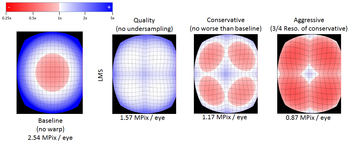
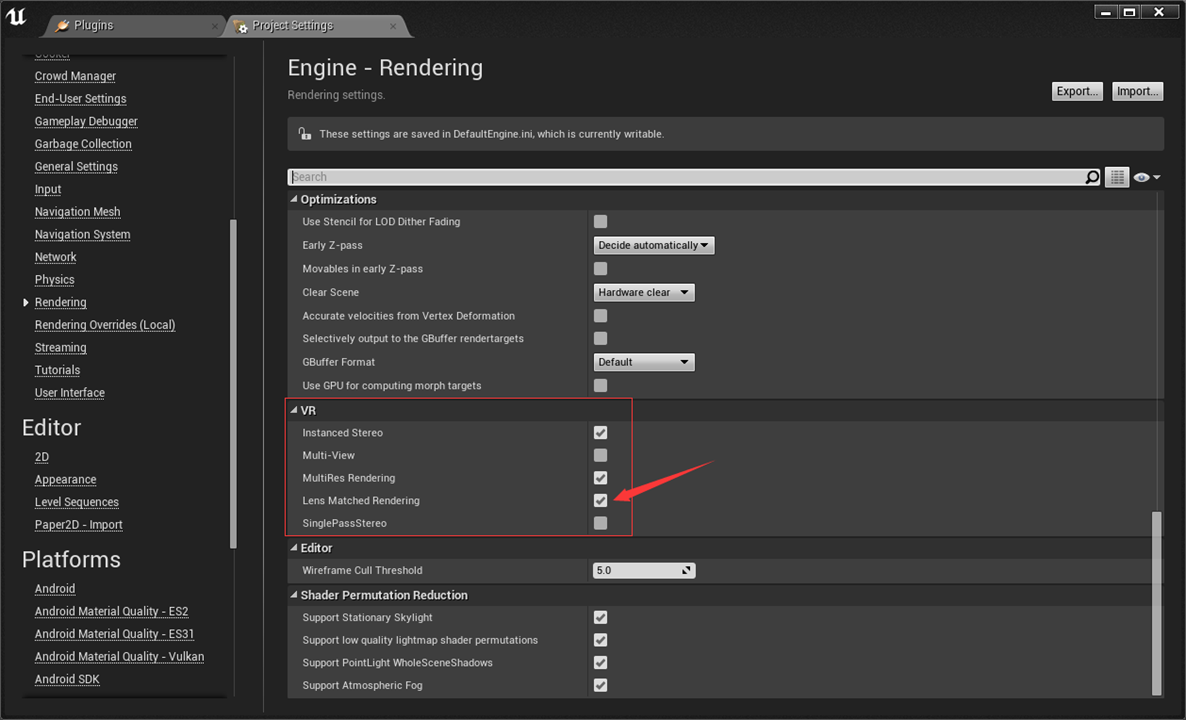
Lens Matched Shading is exposed in UE4 via a renderer property that you will need to enable within your project in order to make it available in the game.. You can find the property setting in the editor menu by following Edit-&gt;Project Settings-&gt;Engine-&gt;Rendering-&gt;VR and checking “Lens Matched Rendering”, as shown in the figure below. Beware that enabling this property will force you to restart the engine and recompile many of the shaders to enable the new support. Once the render property is enabled, you can switch the LMS configuration at any time using the console variable  “vr.LensMatchedShadingRendering” and 1, 2 and 3 select from the Quality, Conservative and Aggressive presets described above.</p>

<p><img src="/assets/images/lms_posts/image_8.png" alt="image alt text" class="align-center" /></p>

<h2 id="integration-overview">Integration Overview</h2>

<p>
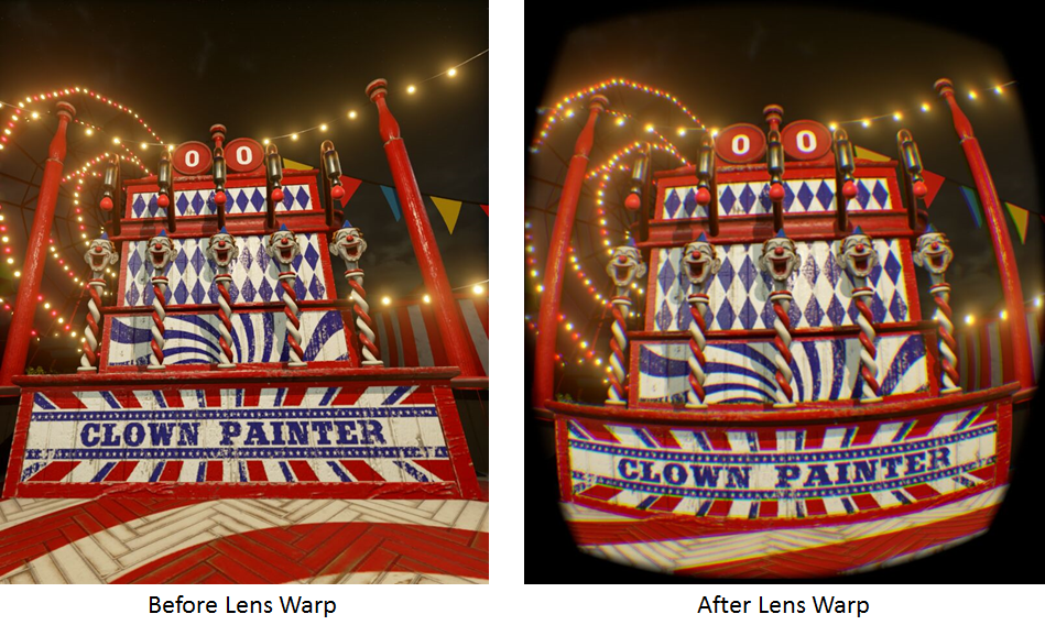
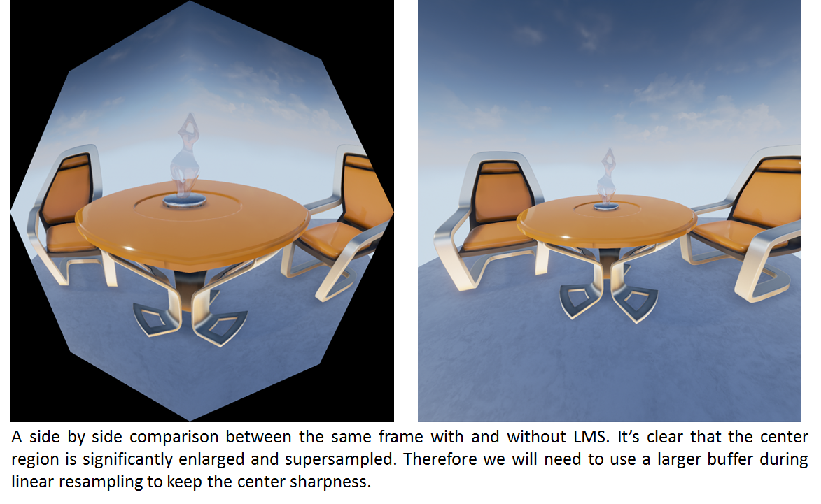
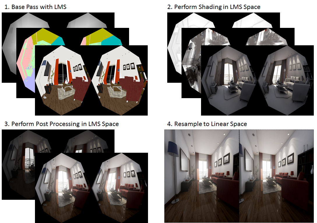
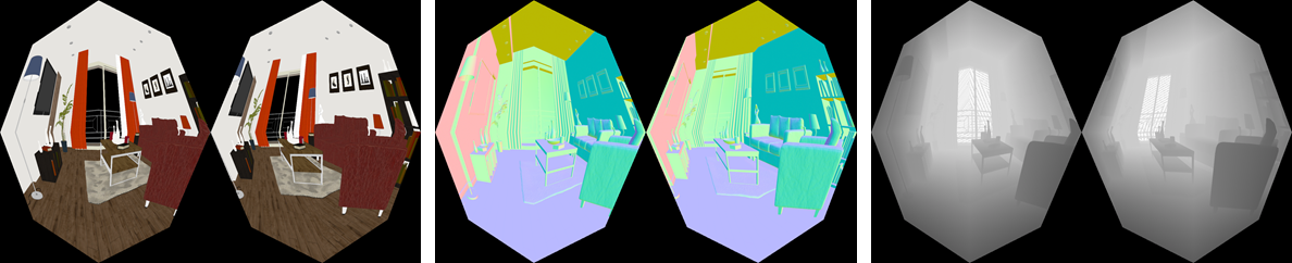
The renderer in Unreal Engine 4 uses deferred shading (note : the new forward shading path added in release 4.14 is out of the scope of this post, though the general strategy of integration stays the same). Integrating LMS into a deferred renderer is fairly simple : <em>w</em> scaling is applied during the GBuffer base pass, which turns all the layers into an octagon shape. Then all shading, lighting, screen space effects (SSAO, SSR) and post processing should ideally be done within the octagon shaped region. Finally, at the end of the rendering pipeline, after all passes have been completed, a full screen resampling operation is performed to unwarp the shaded octagon buffer back to a rectangle for display.</p>

<p><img src="/assets/images/lms_posts/image_9.png" alt="image alt text" class="align-center" /></p>

<p>
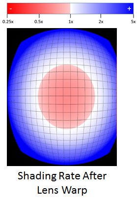
This way most of the shading and pixel processing is done in the area of the octagon, which is much smaller than the full rectangle, as explained in the pre-set configuration section.</p>

<p>Because working in an octagon-shaped clip space introduces an additional coordinate space, existing shaders must be carefully adjusted. Because LMS changes the definition of the screen-space coordinate system and vertex positions, we have to be really careful with determining whether a given coordinate is in the original linear space, or the octagon-shaped LMS space when accessing them in the shaders. When LMS is combined with stereo rendering there is an additional layer of complexity to coordinate conversion since we also need to convert between view space and render target space.</p>

<p>Lastly,  in LMS coordinate space, the depth value of each fragment needs to be adjusted because the w is modified before perspective division. Whenever we need to fetch depth from the depth buffer for things like reconstructing world space position, we also need to remap the Z value fetched to get the depth in linear space. We’ve implemented a helper function that remap Z value from LMS space to linear space called LensMatchedCorrectDeviceZ in VRProjection.usf.</p>

<p>In order to facilitate future integrations, we have defined a generic set of coordinate remapping functions in VRProjection.usf to handle all kinds of circumstances. Because coordinate remapping can be delicate, we have dedicated several subsections below on how to handle certain render passes and practical applications.</p>

<h2 id="linear-and-lms-coordinate-system">Linear and LMS Coordinate System</h2>

<p>
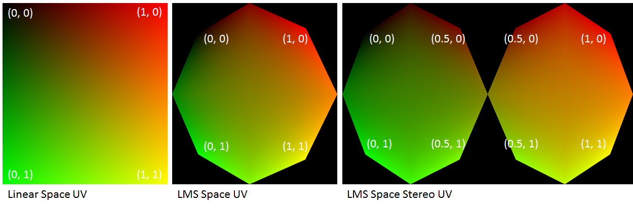
The following figure demonstrates the remapped screen space uv coordinates with modified w. The black regions outside of those octagons will be outside of the render target after resampling to linear space.</p>

<p>In the later text, I will refer to coordinate space as linear space if the space fills the entire rectangularly shaped buffer. And I will refer it as LMS space if it fills only an octagon (or two, in the case of stereo), like shown below.</p>

<p><img src="/assets/images/lms_posts/image_10.png" alt="image alt text" class="align-center" /></p>

<h2 id="infrastructure-support">Infrastructure Support</h2>

<h3 id="vrworks-utilities">VRWorks Utilities</h3>

<p>Our implementation of all VRWorks features into UE4 strives to adhere strictly to the native code-base style for a seamless integration. LMS functionalities have been distributed in the following files:</p>

<ul>
  <li>
    <p>VRProjection.h / .cpp: All LMS utility functions such as viewport size calculation based on warp coefficients and calculating the required constant buffer data.</p>
  </li>
  <li>
    <p>VRProjection.usf: All the LMS related shader code, which includes FastGS implementation and coordinate remap</p>
  </li>
</ul>

<h3 id="multiple-viewports-and-modified-w">Multiple Viewports and Modified W</h3>

<p>Clip-space w modification requires several technologies built into Pascal GPUs, namely Fast Geometry Shaders to broadcast geometry into multiple viewports and obviously the ability to modify w in clip space. On the engine RHI level, it also needs the ability to bind multiple viewports and scissor rects simultaneously. The following sub-sections detail the requisite D3D11 RHI functions. Note most of these functions were only implemented in D3D11.</p>

<p>The following two RHI functions are used for setting up multiple viewports and scissor rects.</p>

<div class="language-c++ highlighter-rouge"><div class="highlight"><pre class="highlight"><code><span class="k">virtual</span> <span class="kt">void</span> <span class="nf">RHISetMultipleViewports</span><span class="p">(</span><span class="n">uint32</span> <span class="n">Count</span><span class="p">,</span> <span class="k">const</span> <span class="n">FViewportBounds</span><span class="o">*</span> <span class="n">Data</span><span class="p">);</span>

<span class="k">virtual</span> <span class="kt">void</span> <span class="nf">RHISetMultipleScissorRects</span><span class="p">(</span><span class="kt">bool</span> <span class="n">bEnable</span><span class="p">,</span> <span class="n">uint32</span> <span class="n">Num</span><span class="p">,</span> <span class="k">const</span> <span class="n">FIntRect</span><span class="o">*</span> <span class="n">Rects</span><span class="p">);</span>
</code></pre></div></div>

<p>The next two functions are for enabling the clip space w modification, the first one is used for single view rendering and the second one is used for stereo rendering such as in Instanced Stereo. The Conf variable includes warp coefficients A and B for all the viewports. They both call NvAPI_D3D_SetModifiedWMode underneath to enable modified w mode. The interested reader can look at their implementations in D3D11Commands.cpp, and refer to the VRWorks SDK for detailed explanation of the modified w mode.</p>

<div class="language-c++ highlighter-rouge"><div class="highlight"><pre class="highlight"><code><span class="k">virtual</span> <span class="kt">void</span> <span class="nf">RHISetModifiedWMode</span><span class="p">(</span><span class="k">const</span> <span class="n">FLensMatchedShading</span><span class="o">::</span><span class="n">Configuration</span><span class="o">&amp;</span> <span class="n">Conf</span><span class="p">,</span> <span class="k">const</span> <span class="kt">bool</span> <span class="n">bWarpForward</span><span class="p">,</span> <span class="k">const</span> <span class="kt">bool</span> <span class="n">bEnable</span><span class="p">);</span>
<span class="k">virtual</span> <span class="kt">void</span> <span class="nf">RHISetModifiedWModeStereo</span><span class="p">(</span><span class="k">const</span> <span class="n">FLensMatchedShading</span><span class="o">::</span><span class="n">StereoConfiguration</span><span class="o">&amp;</span> <span class="n">Conf</span><span class="p">,</span> <span class="k">const</span> <span class="kt">bool</span> <span class="n">bWarpForward</span><span class="p">,</span> <span class="k">const</span> <span class="kt">bool</span> <span class="n">bEnable</span><span class="p">);</span>
</code></pre></div></div>

<h3 id="fast-geometry-shaders">Fast Geometry Shaders</h3>

<p>Support for FastGS is another critica part in implementing LMS in UE4 and it needs to be applied to every types of geometric primitive used in rendering</p>

<p>The following is the RHI function creates a Fast Geometry Shader, which invokes NvAPI_D3D11_CreateGeometryShaderEx_2 underneath.</p>

<div class="language-c++ highlighter-rouge"><div class="highlight"><pre class="highlight"><code><span class="k">virtual</span> <span class="n">FGeometryShaderRHIRef</span> <span class="nf">RHICreateFastGeometryShader_2</span><span class="p">(</span><span class="k">const</span> <span class="n">TArray</span><span class="o">&lt;</span><span class="n">uint8</span><span class="o">&gt;&amp;</span> <span class="n">Code</span><span class="p">,</span> <span class="n">uint32</span> <span class="n">Usage</span><span class="p">);</span>
</code></pre></div></div>

<p>Implementing a Fast Geometry Shader on the C++ side is similar to shaders in UE4. We added a static const boolean called IsFastGeometryShader to all shader classes, with a default value set to false. When the value is set to true, the D3D shader compilation process will invoke RHICreateFastGeometryShader_2 to create a Fast Geometry Shader for us. The following is an example FastGS implementation for base pass geometry. Notice the highlighted line that explicitly specifies FastGS type.</p>

<div class="language-c++ highlighter-rouge"><div class="highlight"><pre class="highlight"><code><span class="c1">// BasePassRendering.h</span>
<span class="k">template</span><span class="o">&lt;</span><span class="k">typename</span> <span class="nc">LightMapPolicyType</span><span class="p">&gt;</span>
<span class="k">class</span> <span class="nc">TBasePassFastGS</span> <span class="o">:</span> <span class="k">public</span> <span class="n">TBasePassFastGeometryShaderPolicyParamType</span><span class="o">&lt;</span><span class="k">typename</span> <span class="n">LightMapPolicyType</span><span class="o">::</span><span class="n">VertexParametersType</span><span class="o">&gt;</span>
<span class="p">{</span>
  <span class="n">DECLARE_SHADER_TYPE</span><span class="p">(</span><span class="n">TBasePassFastGS</span><span class="p">,</span> <span class="n">MeshMaterial</span><span class="p">);</span>
  <span class="cm">/*
    Skipped…
  */</span>

  <span class="k">static</span> <span class="k">const</span> <span class="kt">bool</span> <span class="n">IsFastGeometryShader</span> <span class="o">=</span> <span class="nb">true</span><span class="p">;</span>
<span class="p">};</span>
</code></pre></div></div>

<p>We have created helper marcos in order to facilitate the implementation of FastGS in shader files. The following is an example FastGS implemetation for base pass rendering and it should be put into the vertex shader files of the corresponding geometry types.</p>

<div class="language-c++ highlighter-rouge"><div class="highlight"><pre class="highlight"><code><span class="c1">// BasePassVertexShader.usf</span>
<span class="n">VRPROJECT_CREATE_FASTGS</span><span class="p">(</span><span class="n">VRProjectFastGS</span><span class="p">,</span>	<span class="c1">// Name of fast gs entry point</span>
   	<span class="n">FBasePassVSToPS</span><span class="p">,</span>              	<span class="c1">// Input struct</span>
   	<span class="n">Position</span><span class="p">)</span> 	                 	<span class="c1">// name of position attribute</span>
</code></pre></div></div>

<p>The FastGS calculates the viewport mask of a given triangle based on the positions of its vertices, before passing it through the pipeline. For reference, you can find the instantiated macro in VRProjection.usf.</p>

<p>Finally we need to hookup the FastGS to all drawing policies and other relevant places. Please refer to the source code for details.</p>

<h3 id="sceneview-and-constant-buffer-setup">SceneView and Constant Buffer Setup</h3>

<p>We’ve added a few new members to FSceneView in order to keep track of numerous LMS related states, like its configurations, multiple viewports and scissors. A really important function of FSceneView is:</p>

<p>void FSceneView::SetupVRProjection(int32 ViewportGap);</p>

<p>It performs all the necessary setup for Lens Matched Shading, including calculating the multiple viewports and scissor sizes based on the configuration currently selected.</p>

<p>The following two helper functions enable and disable LMS mode before and after a draw call. EndVRProjectionStates must be called after each renderpass in order to restore the state of the scissors and w. Incorrect LMS render-state results in very distorted images.</p>

<div class="language-c++ highlighter-rouge"><div class="highlight"><pre class="highlight"><code><span class="kt">void</span> <span class="n">FSceneView</span><span class="o">::</span><span class="n">BeginVRProjectionStates</span><span class="p">(</span><span class="n">FRHICommandList</span><span class="o">&amp;</span> <span class="n">RHICmdList</span><span class="p">)</span> <span class="k">const</span><span class="p">;</span>
<span class="kt">void</span> <span class="n">FSceneView</span><span class="o">::</span><span class="n">EndVRProjectionStates</span><span class="p">(</span><span class="n">FRHICommandList</span><span class="o">&amp;</span> <span class="n">RHICmdList</span><span class="p">)</span> <span class="k">const</span><span class="p">;</span>
</code></pre></div></div>

<p>Finally, we have added a number of new members to the view constant buffer, which are necessary for both the FastGS and coordinate remap functions in VRProjection.usf. They are initialized along with the other members in FViewInfo::CreateUniformBuffer(). Please refer to the source code for details.</p>

<h3 id="full-view-octagon-instead-of-rectangle">Full View Octagon (instead of Rectangle)</h3>

<p>In additional to physically based shading and lighting, the UE4 renderer relies heavily on all sorts post processing effects to enhance the final rendered results. Originally, these post processing passes were mostly full screen pixel shader passes that are initiated by rendering a quad that covers the entire view. However, since all we have are black pixels outside of the octagon in all buffers, for all full screen passes we only need to operate on pixels that are inside the octagon.</p>

<p>A naive way to do this is to still render a full view quad, but use either the depth or stencil buffer to kill pixels that are outside of the octagon. The downside to this approach is that we would need to bind the depth buffer for a lot of the passes which originally did not have it bound. Similarly, other passes already rely on the stencil buffer for other purposes, preventing us from using it. What we did instead, is directly render an octagon that covers the same area of pixels in the GBuffer directly.</p>

<p><img src="/assets/images/lms_posts/image_11.png" alt="image alt text" class="align-center" /></p>

<p>
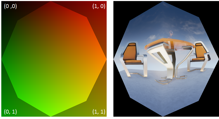
Figure: the octagon is not warping the linear space at all, it simply carves out an octagon shaped region from the linear space so we can use it to directly access the GBuffer.</p>

<p>It’s worth noting that the vertex data that we draw with the octagon is actually in linear space, which means the octagon does not cover the entire UV space. It might sound counter-intuitive at first, but it makes perfect sense, since we need linear space UV to access the GBuffer which is still stored and indexed in a linear buffer! The data stored in the GBuffer, though, is in LMS space.</p>

<h2 id="render-passes">Render Passes</h2>

<p>Broadly speaking, there are two types of rendering passes.</p>

<ol>
  <li>Geometry passes that draws actual geometric primitives to the screen, like the base pass, depth pre-pass, deferred lighting, shadow projection, decals, velocities and so on. For these passes, the general flow is to set up the multiple viewports and scissors as well as enabling modified w mode before invoking the draw call, and restoring those states afterwards. The drawing policy should also be modified to hook up the FastGS properly. Since all these tasks have been encapsulated in helper functions, in practice all that remains to be done looks like this:</li>
</ol>

<div class="language-c++ highlighter-rouge"><div class="highlight"><pre class="highlight"><code><span class="n">View</span><span class="p">.</span><span class="n">BeginVRProjectionStates</span><span class="p">(</span><span class="n">RHICmdList</span><span class="p">);</span> 

<span class="c1">// Invoke draw calls..</span>

<span class="n">View</span><span class="p">.</span><span class="n">EndVRProjectionStates</span><span class="p">(</span><span class="n">RHICmdList</span><span class="p">);</span>
</code></pre></div></div>

<ol>
  <li>Screen space passes such as screen space reflections, screen space ambient occlusion and all the other post processing passes. As previously mentioned, instead of rendering a fullscreen quad, we only cover the smaller octagonal area. For full screen passes that use compute shaders like tiled-based lighting and environmental reflections, we also need to kill threads that work on pixels outside of the octagon.</li>
</ol>

<p>For both types of render passes, shaders need to be aware of LMS space and remap coordinates accordingly.</p>

<h3 id="base-pass">Base Pass</h3>

<p>Getting modified w mode to work in the base pass is quite straightforward. With the infrastructure and RHI support we’ve built, all that needs to be done is modify the SetupBasePassView to set up the multiple viewports and scissors as well as calling RHISetModifiedWMode, as mentioned previously. The resulting GBuffers should look like the following.</p>

<p><img src="/assets/images/lms_posts/image_12.png" alt="image alt text" class="align-center" /></p>

<p>On the shader side, base pass pixel shaders execute code generated from the material graph in the material editor, in which the artists are free to use any information, including pixel depth. The depth in LMS is no longer linear due to w being modified, therefore we had to modify the material graph code generator to generate code that remaps the depth value to linear as well. See the implementation of FHLSLMaterialTranslator::PixelDepth() for details.</p>

<p>One caveat here is that the FastGS occupies the geometry shader slot to perform viewport mask calculation in order to broadcast triangles into multiple viewports. FastGS derives its much improved performance from the restriction imposed on the topology of the geometry: vertices cannot be modified in any way.Therefore, LMS cannot be applied to objects that rely on the functionality of a regular geometry shader. As a workaround, these objects can still be rendered into a linear render target and warped back into the GBuffer.</p>

<h3 id="instanced-stereo">Instanced Stereo</h3>

<p>The Instanced Stereo feature operates by rendering into a single viewport that encompasses both the left and the right views. In the vertex shader, vertices are transformed to clip space with either the left or right view matrices, before being shifted in the x direction to the left or right half of the viewport based on their instance IDs. However, shifting vertices in clip space breaks the modified w calculation since it assumes the clip space spans [-1, 1] in x direction. And shifting changes the clip space span of the left eye to [-1, 0] and the right eye to [0, 1].</p>

<p>
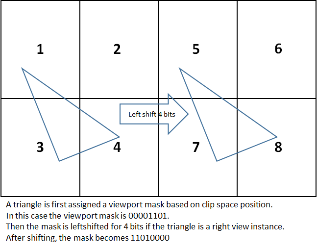
Therefore In order to combine both the LMS and Instanced Stereo techniques we do not shift vertices in the vertex shader and instead use the FastGS to directly broadcast vertices to their appropriate viewports by calculating viewport masks based on their clip space position and instance IDs. Similar to regular instanced stereo which sets a viewport that encompasses both the left and the right view, with LMS we set 8 viewports and 8 scissors simultaneously with the aforementioned RHI functions, with the first 4 viewports belong to the left view and the second 4 belonging to the right. In FastGS, the viewport mask of the first 4 viewports is first computed based on the input vertices’ clip space positions to determine which quadrant(s) of the view the triangle falls into, before being left shifted for 4 bits if the instance belongs to the right view. The following figure demonstrates the process.</p>

<p><img src="/assets/images/lms_posts/image_13.png" alt="image alt text" class="align-center" /></p>

<h3 id="lighting">Lighting</h3>

<p>As previously mentioned, we should perform lighting calculations in LMS space to get the benefit of the flexible shading rate.</p>

<p>In the context of UE4’s engine, LMS only requires changes to 2 types of light sources, fullscreen directional lights and lights with finite shape such as spherical lights and spot lights.</p>

<ul>
  <li>
    <p>Full screen directional lights, we can just render a fullscreen octagon without using FastGS. In the pixel shader however, we need to recalculate the ScreenVector variable per pixel since we need to remap it to the LMS coordinate space.</p>
  </li>
  <li>
    <p>Spherical lights or spot lights, all that’s needed is to call FSceneView::Begin/EndVRProjectionStates before and after the draw call to apply w modification to the geometry being rendered.</p>
  </li>
</ul>

<p>For tile-based lighting with compute shaders, we can improve performance by culling early the compute groups that do not overlap with the octagon. We will also need to remap the tile scale and bias which are used to calculate the tile frustum to the LMS coordinate space. The same process needs to be applied to other full screen compute shader passes, such as environmental reflections.</p>

<h3 id="shadows">Shadows</h3>

<p>Since LMS is not applied to the viewports used for shadow map generation, no changes are required to these passes. For shadow projections, we will need to again hook up FastGS for shadow frustum and set up multiple viewports and scissors as well as enabling modified w mode by calling FSceneView::BeginVRProjectionStates.</p>

<p>In the shadow projection shaders, the only thing worth noting is to make sure to remap screen space position from linear space to LMS space before transforming it to get coordinates in the shadow map.</p>

<h3 id="hzb-construction">HZB Construction</h3>

<p>In UE4 Hierarchical Z Buffer is used to improve the performance of both SSR ray tracing and depth comparison in SSAO. Since both SSR and SSAO require sampling HZB multiple times per pixel, it could cause LMS to incur severe performance costs as each sample would require a remapping of the depth value fetched. Instead, we store the depth values in linear space when creating the HZB, in order to avoid per-sample corrections later.</p>

<h3 id="ssr-and-ssao">SSR and SSAO</h3>

<p>For both Screen Space Reflections and Screen Space Ambient Occlusion, a full-screen octagon should be drawn to ignore the pixels falling outside of the octagon</p>

<p>
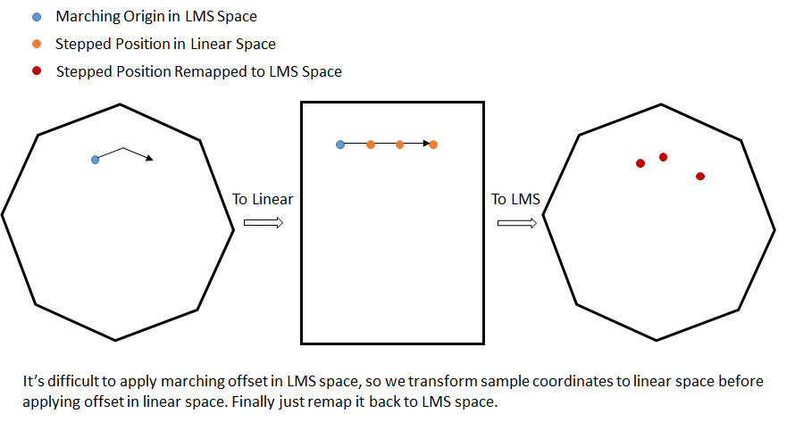
SSR perform screen space ray tracing by marching steps into the HZB along given offsets. However, while sample locations need to be computed in linear space, we are rendering in LMS space. For correct results, we need to remap the marching origin to linear space and apply all the marching offset in linear space. Finally, we need to map the coordinates back to LMS space when fetching values from HZB.</p>

<p>The following figure demonstrates this process.</p>

<p><img src="/assets/images/lms_posts/image_14.png" alt="image alt text" class="align-center" /></p>

<p>SSAO sampling is similarly corrected. For each pixel it samples the HZB value around with a certain offset. Here we also need to remap each sample coordinate from linear space to LMS space before accessing the HZB.</p>

<p>Because the HZB depth values have already been remapped at creation time, the values fetched do not need to be corrected at every sample tap.</p>

<h3 id="other-passes">Other Passes</h3>

<p>Adding LMS to all other full screen passes like temporal AA, tone mapping and so on should generally follow similar principles with SSR and SSAO:</p>

<ul>
  <li>
    <p>Fullscreen octagon should be rendered instead of a rectangle to avoid processing pixels outside of the LMS octagon</p>
  </li>
  <li>
    <p>Any texture coordinate offset should be applied in linear space and then converted back to LMS space.</p>
  </li>
  <li>
    <p>Z value fetched from depth buffer (but not HZB) should be remapped from LMS space back to linear space, for example when reconstructing world space position from depth.</p>
  </li>
  <li>
    <p>All data passed in from the octagon vertex shader is in linear space! So pixel shader input parameters like SvPosition and ScreenPos needs to be remapped to LMS space before using them with other data in the GBuffer which is also in LMS space. On the other hand, they don’t need to be remapped if used to fetch data from the GBuffer, which is stored and indexed in linear space. <strong>Concisely, use linear space coordinates to fetch from texture, use LMS space coordinates to do calculations.</strong></p>
  </li>
</ul>

<p>For other passes that render geometric primitives, just make sure to set up the viewports, scissors, and FastGS and enable modified w mode.</p>

<h3 id="bloom">Bloom</h3>

<p>Blooms and blurs are a different type of screen-space effects that require a dedicated section. UE4 does bloom by blurring several textures with different mip scale. The numerical errors introduced by coordinate remapping are compounded for each mip scaled added, which will make the final bloom skewed.</p>

<p>The solution is that we first resample the bloom setup texture back to linear space and perform all blurring and downsampling in linear space instead. It will be slightly more expensive, but considering bloom is typically computed at quarter resolution to begin with, it should not be cause for too much concern</p>

<h3 id="linear-resampling">Linear Resampling</h3>

<p>We leverage and modify the existing PostProcessUpscale pass to perform the final resampling back to linear space. All that’s needed is to remap texture coordinates from linear space to LMS space before fetching from the render target.</p>]]></content><author><name>Edward Liu</name><email>shiqiu1105@gmail.com</email></author><category term="Virtual Reality" /><category term="Unreal Engine" /><category term="Rendering" /><summary type="html"><![CDATA[Continuing the seris on LMS and UE4 integration, this time we take a deep dive into the details of integration into UE4. The original post can be viewed here.]]></summary></entry><entry><title type="html">Lens Matched Shading and Unreal Engine 4 Integration (Part 3)</title><link href="http://behindthepixels.io/Lens-Matched-Shading-and-UE4-Integration-P3/" rel="alternate" type="text/html" title="Lens Matched Shading and Unreal Engine 4 Integration (Part 3)" /><published>2017-01-18T00:00:00+00:00</published><updated>2017-01-18T00:00:00+00:00</updated><id>http://behindthepixels.io/Lens-Matched-Shading-and-UE4-Integration-P3</id><content type="html" xml:base="http://behindthepixels.io/Lens-Matched-Shading-and-UE4-Integration-P3/"><![CDATA[<p>The last post about LMS and UE4 integration, this time we focus on some important optimization strategies. The original post can be viewed <a href="https://developer.nvidia.com/lens-matched-shading-and-unreal-engine-4-integration-part-3">here</a>.</p>

<h2 id="optimizations">Optimizations</h2>

<h3 id="boundary-masks">Boundary Masks</h3>

<p>One important thing that we have left out until now is that the w modification alone will not reduce any shading because it only affects the way geometries are projected to the screen. So it would still render a full rectangle, even though the four corners will be outside of the render target after resampling the image from LMS space to linear space. Therefore we also have to avoid rendering to pixels that fall outside of the LMS octagon for drawcalls that render geometric promitives.</p>

<p>For this purpose we render a boundary mask to the depth buffer, even before the Z pre-pass, setting the depth value outside of the octagon to the near plane, so no subsequent passes will render to those pixels. For detailed implementation details please refer to the source code in ModifiedWBoundaryMask.cpp and ModifiedBoundaryMask.usf.</p>

<h3 id="deferred-light-stencil-culling">Deferred Light Stencil Culling</h3>

<p>One of the things that the boundary mask in the depth buffer couldn’t help with is deferred lighting. When rendering a stenciled light geometry such as a sphere or a cone, the engine determines whether the camera is inside the light geometry or not. If the camera is inside the geometry, we will have to set the depth test to always pass. So the boundary mask will be trivially passed as well. We could choose to do the octagon inside-outside test in the lighting shader, however this solution is less than optimal, because of the expensive per-pixel LMS remapping</p>

<p>Instead we can populate a stencil buffer with the same octagonal boundary and ust it to cull cull away those regions out of the octagon during the lighting pass.</p>

<h3 id="super-sampling-during-linear-resampling">Super-sampling During Linear Resampling</h3>

<p>As we have shown, LMS reduces the sampling rate in the peripheral area, but can also increase it around the fovea. before applying the final lens distortion to our final frame, we have to convert render target from LMS back into linear space. However, if we were to convert the LMS octagon to the original viewport size, we would lose the benefits of having super-sampled the central area. Ideally, we’d like to fuse our resampling to linear step together with the HMD lens distortion function, although it is difficult because the latter is typically locked inside the HMD run-time compositor software and it performs other optimizations like time warp for us.</p>

<p><img src="/assets/images/lms_posts/image_15.png" alt="image alt text" class="align-center" /></p>

<p>Instead, we work around this limitation by resampling the LMS buffer into a target that is larger than the original buffer size. We have added another console variable, vr.LensMatchedShadingUnwarpScale, to scale the resolution of the buffer. Typically, values between 1.3 to 1.5 would maintain the center sharpness reasonably well, while not impacting performance too much.</p>

<h2 id="miscellaneous-things">Miscellaneous Things</h2>

<h3 id="viewport-size-quantization">Viewport Size Quantization</h3>

<p>When calculating the viewport sizes, the UE4 always quantizes it to make both the width and height divisible by 4. However, because LMS calculates a new viewport based on the quantized viewport size, the result will not be divisible by 4. For this reason, we will have to quantize the size of the LMS viewport to multiples of 4, otherwise we will have lots of artifacts like bloom not being aligned with the image, decals being offset slightly and so on.</p>

<p>However, we can’t simply adjust the viewport width and height, since doing that will make the LMS configuration inconsistent with the actual calculated viewport. So we will have to adjust the corresponding fields in the LMS configuration as well. Please refer to implementation in FSceneView::SetupVRProjection for details.</p>

<h3 id="viewport-gap">Viewport Gap</h3>

<p>Some HMD headsets like the Oculus Rift put a gap of a certain number of pixels between the left and right views, which UE4 takes into account when calculating the viewports for both the left and right view. LMS obviously needs to be aware of this too when calculating its viewport.</p>

<p>In the current integrations of LMS in UE4, we always run the PostProcessUpscale pass to perform linear resampling. Therefore, we completely ignore the viewport gap during viewport calculation, and rely solely on the resampling pass to position the two views slightly away from each other. This tremendously reduces the complexity and chances of error of mixing viewport gap, quantization as well as LMS viewport calculation conflating issues, while providing us with the same result in performance.</p>

<h1 id="performance">Performance</h1>

<p>The following chart demonstrates some performance statistics of running LMS on a number of UE4 scenes. All the data below was collected using GTX1080, rendering at 1512x1680 resolution as recommended by Vive. We can clearly see that LMS provide a big shrink in terms of frame time, while subjectively also increasing perceived rendering quality. We also compare the most aggressive setting between LMS and MRS, and demonstrate that LMS produces better performance and perceived quality.</p>

<p><img src="/assets/images/lms_posts/image_16.png" alt="image alt text" class="align-center" /></p>

<p><img src="/assets/images/lms_posts/image_17.png" alt="image alt text" class="align-center" /></p>

<p>Of note, reduced frame time isn’t as much as the amount of pixels shaded. There are many reasons for this:</p>

<ul>
  <li>
    <p>Pixel shading is only part of the frame. If your pipeline is geometry bound or even CPU bound, Lens Matched Shading isn’t likely to help.</p>
  </li>
  <li>
    <p>The coordinate remap between linear space and LMS space definitely isn’t free, and we have to do it quite a few times in passes like SSR and SSAO.</p>
  </li>
  <li>
    <p>The additional pass for resampling to linear space, especially when done at a much higher resolution in order to maintain center sharpness can impact performance too.</p>
  </li>
</ul>

<p>Nonetheless, we believe that in most circumstances LMS will deliver faster rendering and higher quality at the same time.</p>

<h1 id="future-work-and-conclusion">Future Work and Conclusion</h1>

<p>We believe that with the trend of higher and higher resolution displays and virtual reality, uniform shading rate across the image will become too expensive and unnecessary. Lens Matched Shading with clip space w modification is one way to manipulate the shading rate distribution to match what the viewer  is actually looking at. As future work, we are actively exploring other potentially more effective ways to redistribute shading rate, such as foveated rendering also can potentially be combined with LMS.</p>]]></content><author><name>Edward Liu</name><email>shiqiu1105@gmail.com</email></author><category term="Virtual Reality" /><category term="Unreal Engine" /><category term="Rendering" /><summary type="html"><![CDATA[The last post about LMS and UE4 integration, this time we focus on some important optimization strategies. The original post can be viewed here.]]></summary></entry><entry><title type="html">Onward!</title><link href="http://behindthepixels.io/Onward/" rel="alternate" type="text/html" title="Onward!" /><published>2016-02-20T00:00:00+00:00</published><updated>2016-02-20T00:00:00+00:00</updated><id>http://behindthepixels.io/Onward</id><content type="html" xml:base="http://behindthepixels.io/Onward/"><![CDATA[<p>Welcome to my new site! I created my previous website <a href="http://www.edxgraphics.com/">edxgraphics.com</a> in 2012 to serve as my portfolio when I was applying grad school. And I’ve been sporadically updating it with technical blogs, stunning images rendered by my softwares, as well as information on my projects.</p>

<p>That site was built with weebly, which is really friendly for web programming layman like myself with its “drag-and-drop” approach of creating the site. However, it’s become a huge frustration when I needed more advanced feature in my writing, such as code snippets and mathematical equations. It’s even a bigger hassel to maintain a nested sub menu structure in my project pages. So I decided to switch to using Hugo. So here the new site was born!</p>

<p>I will start selectively migrating stuff from my previous site here, and also keep updating it with fun things related to graphics, vision, and other general topics that I found interesting.</p>

<p>Edward</p>]]></content><author><name>Edward Liu</name><email>shiqiu1105@gmail.com</email></author><category term="Untagged" /><summary type="html"><![CDATA[Welcome to my new site! I created my previous website edxgraphics.com in 2012 to serve as my portfolio when I was applying grad school. And I’ve been sporadically updating it with technical blogs, stunning images rendered by my softwares, as well as information on my projects.]]></summary></entry><entry><title type="html">Immediate mode GUI</title><link href="http://behindthepixels.io/IMGUI/" rel="alternate" type="text/html" title="Immediate mode GUI" /><published>2015-02-19T00:00:00+00:00</published><updated>2015-02-19T00:00:00+00:00</updated><id>http://behindthepixels.io/IMGUI</id><content type="html" xml:base="http://behindthepixels.io/IMGUI/"><![CDATA[<p>Recently I have been re-writing my own GUI library. This time I took an immediate mode approach rather than the traditionally “retained mode”. I am quite happy with what I’ve got so far, both in terms of functionality and aesthetic. The following is a screenshot.</p>

<p>One of the most welcoming feature of immediate mode GUI is it’s ease of use. For example, with EDXGui, to add dialogs the same as the screenshot above, all the code that’s required are below. The structure of the dialog matches with your code intuitively and the layout is auto-generated.</p>

<div class="language-c++ highlighter-rouge"><div class="highlight"><pre class="highlight"><code>	<span class="n">EDXGui</span><span class="o">::</span><span class="n">BeginFrame</span><span class="p">();</span>
	<span class="n">EDXGui</span><span class="o">::</span><span class="n">BeginDialog</span><span class="p">();</span>

	<span class="n">EDXGui</span><span class="o">::</span><span class="n">Text</span><span class="p">(</span><span class="s">"Right docked dialog"</span><span class="p">);</span>

	<span class="k">static</span> <span class="n">string</span> <span class="nf">buf</span><span class="p">(</span><span class="s">""</span><span class="p">);</span>
	<span class="n">EDXGui</span><span class="o">::</span><span class="n">Text</span><span class="p">(</span><span class="n">buf</span><span class="p">.</span><span class="n">c_str</span><span class="p">());</span>
	<span class="k">if</span> <span class="p">(</span><span class="n">EDXGui</span><span class="o">::</span><span class="n">Button</span><span class="p">(</span><span class="s">"Button 1"</span><span class="p">))</span>
		<span class="n">buf</span> <span class="o">=</span> <span class="s">"Button 1 clicked"</span><span class="p">;</span>
	<span class="k">if</span> <span class="p">(</span><span class="n">EDXGui</span><span class="o">::</span><span class="n">Button</span><span class="p">(</span><span class="s">"Button 2"</span><span class="p">))</span>
		<span class="n">buf</span> <span class="o">=</span> <span class="s">"Button 2 clicked"</span><span class="p">;</span>

	<span class="k">static</span> <span class="kt">float</span> <span class="n">counter1</span> <span class="o">=</span> <span class="mi">0</span><span class="p">;</span>
	<span class="k">static</span> <span class="kt">int</span> <span class="n">counter2</span> <span class="o">=</span> <span class="mi">0</span><span class="p">;</span>

	<span class="c1">//EDXGui::Text("Value 1: %f", counter1);</span>
	<span class="n">EDXGui</span><span class="o">::</span><span class="n">Slider</span><span class="o">&lt;</span><span class="kt">float</span><span class="o">&gt;</span><span class="p">(</span><span class="s">"Float slider"</span><span class="p">,</span> <span class="o">&amp;</span><span class="n">counter1</span><span class="p">,</span> <span class="mf">0.0</span><span class="n">f</span><span class="p">,</span> <span class="mf">20.0</span><span class="n">f</span><span class="p">);</span>
	<span class="c1">//EDXGui::Text("Value 2: %i", counter2);</span>
	<span class="n">EDXGui</span><span class="o">::</span><span class="n">Slider</span><span class="o">&lt;</span><span class="kt">int</span><span class="o">&gt;</span><span class="p">(</span><span class="s">"Int slider"</span><span class="p">,</span> <span class="o">&amp;</span><span class="n">counter2</span><span class="p">,</span> <span class="mi">0</span><span class="p">,</span> <span class="mi">5</span><span class="p">);</span>

	<span class="k">static</span> <span class="kt">bool</span> <span class="n">show</span> <span class="o">=</span> <span class="nb">false</span><span class="p">;</span>
	<span class="k">if</span> <span class="p">(</span><span class="n">EDXGui</span><span class="o">::</span><span class="n">CollapsingHeader</span><span class="p">(</span><span class="s">"Collapsing Header"</span><span class="p">,</span> <span class="n">show</span><span class="p">))</span>
	<span class="p">{</span>
		<span class="k">static</span> <span class="kt">bool</span> <span class="n">checked</span> <span class="o">=</span> <span class="nb">false</span><span class="p">;</span>
		<span class="n">EDXGui</span><span class="o">::</span><span class="n">CheckBox</span><span class="p">(</span><span class="s">"Check Box"</span><span class="p">,</span> <span class="n">checked</span><span class="p">);</span>

		<span class="k">static</span> <span class="kt">int</span> <span class="n">radioVal</span><span class="p">;</span>
		<span class="n">EDXGui</span><span class="o">::</span><span class="n">RadioButton</span><span class="p">(</span><span class="s">"Radio Button 1"</span><span class="p">,</span> <span class="mi">1</span><span class="p">,</span> <span class="n">radioVal</span><span class="p">);</span>
		<span class="n">EDXGui</span><span class="o">::</span><span class="n">RadioButton</span><span class="p">(</span><span class="s">"Radio Button 2"</span><span class="p">,</span> <span class="mi">2</span><span class="p">,</span> <span class="n">radioVal</span><span class="p">);</span>
		<span class="n">EDXGui</span><span class="o">::</span><span class="n">RadioButton</span><span class="p">(</span><span class="s">"Radio Button 3"</span><span class="p">,</span> <span class="mi">3</span><span class="p">,</span> <span class="n">radioVal</span><span class="p">);</span>

		<span class="k">static</span> <span class="kt">bool</span> <span class="n">show2</span> <span class="o">=</span> <span class="nb">true</span><span class="p">;</span>
		<span class="k">if</span> <span class="p">(</span><span class="n">EDXGui</span><span class="o">::</span><span class="n">CollapsingHeader</span><span class="p">(</span><span class="s">"Collapsing Header 2"</span><span class="p">,</span> <span class="n">show2</span><span class="p">))</span>
		<span class="p">{</span>
			<span class="n">EDXGui</span><span class="o">::</span><span class="n">Button</span><span class="p">(</span><span class="s">"Hidden Button"</span><span class="p">);</span>
			<span class="n">EDXGui</span><span class="o">::</span><span class="n">CloseHeaderSection</span><span class="p">();</span>
		<span class="p">}</span>

		<span class="n">EDXGui</span><span class="o">::</span><span class="n">CloseHeaderSection</span><span class="p">();</span>
	<span class="p">}</span>

	<span class="k">static</span> <span class="kt">int</span> <span class="n">selected</span> <span class="o">=</span> <span class="mi">0</span><span class="p">;</span>
	<span class="n">ComboBoxItem</span> <span class="n">items</span><span class="p">[]</span> <span class="o">=</span> <span class="p">{</span>
			<span class="p">{</span> <span class="mi">1</span><span class="p">,</span> <span class="s">"Item 1"</span> <span class="p">},</span>
			<span class="p">{</span> <span class="mi">2</span><span class="p">,</span> <span class="s">"Item 2"</span> <span class="p">},</span>
			<span class="p">{</span> <span class="mi">3</span><span class="p">,</span> <span class="s">"Item 3"</span> <span class="p">},</span>
	<span class="p">};</span>
	<span class="n">EDXGui</span><span class="o">::</span><span class="n">ComboBox</span><span class="p">(</span><span class="s">"Combo box"</span><span class="p">,</span> <span class="n">items</span><span class="p">,</span> <span class="mi">3</span><span class="p">,</span> <span class="n">selected</span><span class="p">);</span>


	<span class="k">static</span> <span class="n">string</span> <span class="n">textBuf1</span><span class="p">(</span><span class="s">"Text field 1"</span><span class="p">);</span>
	<span class="k">static</span> <span class="n">string</span> <span class="n">textBuf2</span><span class="p">(</span><span class="s">"Text field 2"</span><span class="p">);</span>
	<span class="n">EDXGui</span><span class="o">::</span><span class="n">InputText</span><span class="p">(</span><span class="n">textBuf1</span><span class="p">);</span>
	<span class="n">EDXGui</span><span class="o">::</span><span class="n">InputText</span><span class="p">(</span><span class="n">textBuf2</span><span class="p">);</span>

	<span class="k">static</span> <span class="kt">int</span> <span class="n">digitInput</span><span class="p">;</span>
	<span class="n">EDXGui</span><span class="o">::</span><span class="n">InputDigit</span><span class="p">(</span><span class="n">digitInput</span><span class="p">,</span> <span class="s">"Digit input"</span><span class="p">);</span>

	<span class="k">static</span> <span class="kt">bool</span> <span class="n">showSecondDialog</span> <span class="o">=</span> <span class="nb">true</span><span class="p">;</span>
	<span class="n">EDXGui</span><span class="o">::</span><span class="n">CheckBox</span><span class="p">(</span><span class="s">"Multiple Dialog"</span><span class="p">,</span> <span class="n">showSecondDialog</span><span class="p">);</span>

	<span class="k">static</span> <span class="kt">bool</span> <span class="n">showConsole</span> <span class="o">=</span> <span class="nb">true</span><span class="p">;</span>
	<span class="n">EDXGui</span><span class="o">::</span><span class="n">CheckBox</span><span class="p">(</span><span class="s">"Show Console"</span><span class="p">,</span> <span class="n">showConsole</span><span class="p">);</span>

	<span class="n">EDXGui</span><span class="o">::</span><span class="n">EndDialog</span><span class="p">();</span>

	<span class="k">if</span> <span class="p">(</span><span class="n">showSecondDialog</span><span class="p">)</span>
	<span class="p">{</span>
		<span class="n">EDXGui</span><span class="o">::</span><span class="n">BeginDialog</span><span class="p">(</span><span class="n">LayoutStrategy</span><span class="o">::</span><span class="n">Floating</span><span class="p">);</span>
		<span class="p">{</span>
			<span class="n">EDXGui</span><span class="o">::</span><span class="n">Text</span><span class="p">(</span><span class="s">"Multiple dialogs supported"</span><span class="p">);</span>
			<span class="k">static</span> <span class="n">string</span> <span class="n">multiLineText</span> <span class="o">=</span> <span class="s">"Multiple lines of texts and wrapped texts supported:</span><span class="se">\n</span><span class="s">"</span><span class="p">;</span>

			<span class="k">if</span> <span class="p">(</span><span class="n">EDXGui</span><span class="o">::</span><span class="n">Button</span><span class="p">(</span><span class="s">"Add Texts"</span><span class="p">))</span>
				<span class="n">multiLineText</span> <span class="o">+=</span> <span class="s">"Adding more texts! "</span><span class="p">;</span>

			<span class="k">static</span> <span class="kt">float</span> <span class="n">scroller</span> <span class="o">=</span> <span class="mf">0.0</span><span class="n">f</span><span class="p">;</span>
			<span class="k">static</span> <span class="kt">int</span> <span class="n">contentHeight</span> <span class="o">=</span> <span class="mi">0</span><span class="p">;</span>
			<span class="n">EDXGui</span><span class="o">::</span><span class="n">BeginScrollableArea</span><span class="p">(</span><span class="mi">320</span><span class="p">,</span> <span class="n">contentHeight</span><span class="p">,</span> <span class="n">scroller</span><span class="p">);</span>

			<span class="n">EDXGui</span><span class="o">::</span><span class="n">MultilineText</span><span class="p">(</span><span class="n">multiLineText</span><span class="p">.</span><span class="n">c_str</span><span class="p">());</span>

			<span class="n">EDXGui</span><span class="o">::</span><span class="n">EndScrollableArea</span><span class="p">(</span><span class="mi">320</span><span class="p">,</span> <span class="n">contentHeight</span><span class="p">,</span> <span class="n">scroller</span><span class="p">);</span>
		<span class="p">}</span>
		<span class="n">EDXGui</span><span class="o">::</span><span class="n">EndDialog</span><span class="p">();</span>
	<span class="p">}</span>

	<span class="k">if</span> <span class="p">(</span><span class="n">showConsole</span><span class="p">)</span>
		<span class="n">EDXGui</span><span class="o">::</span><span class="n">Console</span><span class="p">(</span><span class="s">""</span><span class="p">,</span> <span class="mi">300</span><span class="p">);</span>

	<span class="n">EDXGui</span><span class="o">::</span><span class="n">EndFrame</span><span class="p">();</span>
</code></pre></div></div>

<p>All the tedious work of layout, writing callback events, listeners, data copying and so on, all of which you would have to handle yourself using retained GUI, are handled by the library. EDXGui provides a number of widgets including buttons, sliders, check boxes, radio buttons, and also a number of more complicated ones such as combo boxes, fully featured text/digit input fields, multiple-line texts auto formatting and automatically generated scrollers. Addtionally, it supports multiple dialogs with different layout strategy.</p>

<p>IMGUI is more suitable for applications that re-paint the client area every frame, such as games or CAD apps. Compared with the more traditional Retained Mode GUI (RMGUI) such as Qt, MFC, IMGUI is simpler both in terms of usage and implementation. I have written both and I feel that IMGUI is easier for first-timers who want to create their own GUI library.</p>

<p>I will briefly talk about the differences between RMGUI and IMGUI both in using them and actually implementing them. Starting with using the GUI library, RMGUI typitically requires the user to explicitly initialize every control it has. Every control is an entity that lives in the RAM somewhere and each one holds certain states/data, for instance a button might hold a function delegate for the event it triggers, a slider might have a current value. Addtionally, users need to pay the extra attention copying data to/from the GUI (MVC mode). A typical usage pattern of RMGUI might look like this:</p>

<p><img src="/assets/images/imgui/image_3.png" alt="image alt text" class="align-center" /></p>

<p>IMGUI will appears to be much more “brutal force”. Widges don’t have their own objects in memory, and they are all stateless. Users don’t need to worry about the data transfer between GUI and the app, don’t even need to write a callback function. Each widget is implemented as a function, which is called directly in the Draw() function of the app. The same GUI written with RMGUI would look like this if using IMGUI:</p>

<p><img src="/assets/images/imgui/image_4.png" alt="image alt text" class="align-center" /></p>

<p>In terms of implementing the library, in RMGUI each widget has their own class, which has members to store corresponding data. These classes all implement certain interfaces for IO handling, rendering, data transfering and so on. There is also a GUI manager like class that manages all the widgets, dispatches events and render widgets. In c++ it might look like this:</p>

<p><img src="/assets/images/imgui/image_5.png" alt="image alt text" class="align-center" /></p>

<p>The logic is indeed a little convoluted here, compared with IMGUI, in which each widget is simply a giant function that handles both IO interaction and rendering. They are also stateless, all states are stored in the app itself. The code might look like this:</p>

<p><img src="/assets/images/imgui/image_6.png" alt="image alt text" class="align-center" /></p>

<p>The code of IMGUI mode tend to be much shorter but more intensive, every thing is packed in a single function. In my own EDXGui, which has a fully featured text input field, there are only hundreds lines of code. Since programmers don’t need to deal with writing callbacks and data transfers seperatly, it’s actually simpler to implement.</p>

<p>IMGUI also has its own demerits. IMO animation is awkward to support in IMGUI mode, since widgets are stateless and animations would require widgets to at least keep track of time. It sure can be done with your own extra data structure, just much less intuitive than RMGUI. Some also argue that executing UI logic of every widget is wasteful. This might indeed be a concern when implemented poorly (consider re-formatting a multi-million lines string every frame).</p>

<p>However in practice I found most of the problems have little impact. The OnGUI of Unity Engine actually uses IMGUI mode. So it’s definitely usable in real projects.</p>

<p>Lastly, a good tutorial can be found here: <a href="http://sol.gfxile.net/imgui/">www.iki.fi/sol</a></p>]]></content><author><name>Edward Liu</name><email>shiqiu1105@gmail.com</email></author><category term="GUI" /><category term="C++" /><summary type="html"><![CDATA[Recently I have been re-writing my own GUI library. This time I took an immediate mode approach rather than the traditionally “retained mode”. I am quite happy with what I’ve got so far, both in terms of functionality and aesthetic. The following is a screenshot.]]></summary></entry><entry><title type="html">Using Bidirectional path tracing with Irradiance caching in EDXRay</title><link href="http://behindthepixels.io/Bidirectional-Path-Tracing-Irradiance-Caching/" rel="alternate" type="text/html" title="Using Bidirectional path tracing with Irradiance caching in EDXRay" /><published>2014-01-13T00:00:00+00:00</published><updated>2014-01-13T00:00:00+00:00</updated><id>http://behindthepixels.io/Bidirectional-Path-Tracing-Irradiance-Caching</id><content type="html" xml:base="http://behindthepixels.io/Bidirectional-Path-Tracing-Irradiance-Caching/"><![CDATA[<p>Recently I have implemented irradiance caching in the renderer I have been independently developing, EDXRay. This enabled the renderer to synthesize noiseless images in a short amount of time.</p>

<figure style="width: 46%" class="align-left">
  <img src="http://behindthepixels.io/assets/images/bidir_irradiance_cache/image_0.jpg" alt="" />
  <figcaption>Cornell box scene renderer with Irradiance caching. In scenes only contain diffuse objects, this algorithm is particularly efficient.</figcaption>
</figure>

<figure style="width: 46%" class="align-right">
  <img src="http://behindthepixels.io/assets/images/bidir_irradiance_cache/image_1.jpg" alt="" />
  <figcaption>The same scene as the left one, with irradiance samples visualized. Samples distributions are clampled in screen space.</figcaption>
</figure>

<p>The error function follows <a href="http://www.tabellion.org/et/paper/">this work</a>. Irradiance samples are distributed evenly in screen space. My implementation allows me to flexibly integrator used to calculate irradiance. Currently it supports both the 2 GI integrators originally in EDXRay: path tracer and bidirectional path tracer. For scenes where lights can easily be reached by sampling path from the camera, path tracing would suffice. For scenes such as the one below, where the majority of lighting comes from indirect illumination, bidirectional path tracing can produce images that has much less artifacts. All the images shown in this post was rendered with Irradiance Caching, sample distribution clamped at 1.5x to 10x pixel area, and irradiance evaluation sample count is 4096.</p>

<figure style="width: 46%" class="align-left">
  <img src="http://behindthepixels.io/assets/images/bidir_irradiance_cache/image_2.jpg" alt="" />
  <figcaption>Light source is this scene is right below the ceiling, therefore hard to be sampled if tracing paths from camera, resulting a really blotchy image.</figcaption>
</figure>

<figure style="width: 46%" class="align-right">
  <img src="http://behindthepixels.io/assets/images/bidir_irradiance_cache/image_3.jpg" alt="" />
  <figcaption>The same scene as left, with irradiance evaluating with bidirectional path tracing, sample amount of samples used. Since light paths were sampled from the light source too, we can construct a light path more efficiently.</figcaption>
</figure>

<p>Additionally, because bidirectional path tracing (BDPT) with multiple importance sampling is much better at rendering caustics and unidirectional path tracing, therefore in scenes that contain specular objects, using bidirectional path tracing to evaluate irradiance would also be much more efficient than path tracing, as shown below.</p>

<figure style="width: 46%" class="align-left">
  <img src="http://behindthepixels.io/assets/images/bidir_irradiance_cache/image_4.jpg" alt="" />
  <figcaption>Path tracing is not efficient at handling caustics. Scenes with specular objects will be blotchy when using path tracing with irradiance caching.</figcaption>
</figure>
<figure style="width: 46%" class="align-right">
  <img src="http://behindthepixels.io/assets/images/bidir_irradiance_cache/image_5.jpg" alt="" />
  <figcaption>Same scene as left, bidirectional path tracing is more capable of handling specular objects.</figcaption>
</figure>

<p>I am quite happy with the result. And I personally haven’t seen this rendering approach (evaluating irradiance with BDPT in irradiance cache) used in other renderers such as mitsuba, luxray. Probably because caustics can be handled even better by photon mapping. The image below was renderred with irradiance caching, even bidirectional path tracing was used to calculate irradiance, the caustics area below the glass ball still has blotchy artifacts. This is due to caustics is a special form of indirect light that changes quickly over the surface, thus making it not as suitable for interpolation.</p>

<figure style="width: 484px" class="align-center">
  <img src="http://behindthepixels.io/assets/images/bidir_irradiance_cache/image_6.jpg" alt="" />
  <figcaption>Even bidirectional path tracing would fail to efficiently render the caustics below the glass sphere, due to it's not suitable for interpolation.</figcaption>
</figure>

<p>When BDPT is used with irradiance caching, it’s essential that it has all kinds of path sampling techniques. Just like explicitly connecting light vertices to camera lens is important for rendering caustics in normal path tracing (because caustics can be sampled much more easily by light tracing), here connecting light vertices to irradiance sample location is also important to make the algorithm work efficiently.</p>

<p>The next step is to use gradient information of irradiance to do more accurate interpolation. I am also interested in implementing <a href="http://zurich.disneyresearch.com/~wjarosz/publications/schwarzhaupt12practical.html">this work</a>. They seem to be able to development a much efficient error metric.</p>

<p>Lastly, I will post one more image rendered with my irradiance cache integrator, also 4096 bidirectional path samples were used to get irradiance samples. Just for fun, I also did another rendering just visualizing the indirect lighting in the same scene.</p>

<figure class="align-center">
  <img src="http://behindthepixels.io/assets/images/bidir_irradiance_cache/image_7.jpg" alt="" />
  
    <figcaption>Sponza scene renderer with irradiance caching, 5000 path tracing samples used at each irradiance sample location.
</figcaption>
  
</figure>
<figure class="align-center">
  <img src="http://behindthepixels.io/assets/images/bidir_irradiance_cache/image_8.jpg" alt="" />
  
    <figcaption>Same image as above, also showing the interpolated indirect lighting.
</figcaption>
  
</figure>]]></content><author><name>Edward Liu</name><email>shiqiu1105@gmail.com</email></author><category term="Ray Tracing" /><category term="Rendering" /><summary type="html"><![CDATA[Recently I have implemented irradiance caching in the renderer I have been independently developing, EDXRay. This enabled the renderer to synthesize noiseless images in a short amount of time.]]></summary></entry></feed>